Choosing a High-Capacity Ball Feeder System requires more than comparing bowl diameter or motor power. It demands evidence from the production floor.
The International Federation of Robotics reported 541,302 industrial robots installed worldwide in 2023. More than 4.28 million industrial robots were operating globally. These figures show why reliable part presentation matters. A feeder must support automation without creating jams, unstable flow, or excessive noise.
Joseph Engelberger, a pioneer of industrial robotics, said, “I can’t define a robot, but I know one when I see one.” His observation also applies to feeding equipment. A capable system should prove its value through consistent output, not impressive specifications alone.
In practice, selection begins with the ball’s diameter, material, surface finish, weight, and required feed rate. Then examine the track, hopper, sensors, controller, and reject mechanism. A stainless-steel ball may slide differently from a coated polymer ball. Small differences matter.
PMMI industry research continues to highlight labor pressure, machine integration, and flexible automation as important manufacturing concerns. Therefore, a high-capacity solution should connect cleanly with PLCs, vision systems, and downstream assembly equipment.
The target is not maximum speed. It is stable speed.
Some buyers overlook changeover time. That mistake can become expensive. A feeder running at 600 parts per minute may still perform poorly if operators need forty minutes to clear a jam.
This guide evaluates capacity, accuracy, maintainability, noise, energy use, and lifecycle support. It also questions one common assumption: bigger equipment is not always better. A smaller, correctly tuned system may deliver higher real-world availability.
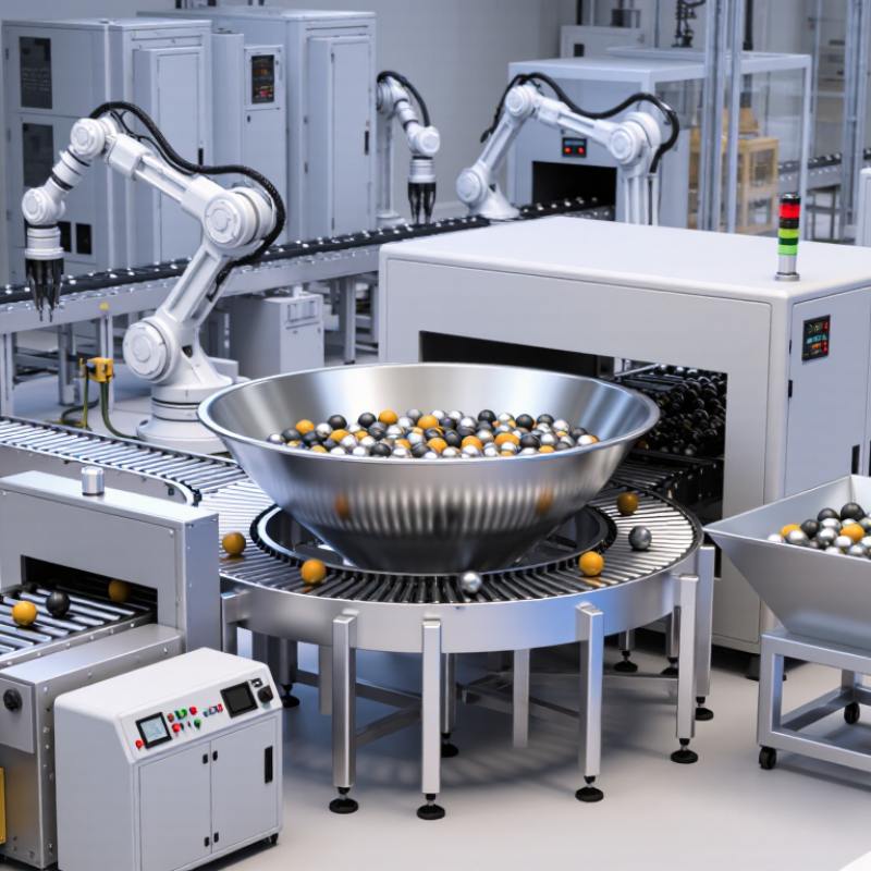
A high-capacity ball feeder system stores, separates, and releases balls at a controlled rate. Its hopper holds bulk material, while an escapement, rotary disc, or vibratory track spaces each ball. Sensors monitor level, speed, and blockages. This creates a steady supply for inspection, assembly, testing, or packaging lines. It also reduces manual loading and protects operators from repetitive handling.
The International Federation of Robotics reported 541,302 industrial robots installed worldwide in 2023. That figure shows the continuing shift toward connected automation. MHI’s 2024 Annual Industry Report also identified digital supply-chain technology as a major investment priority. A feeder should support that direction through clear data, not just higher volume. A practical system records feed rate, stoppages, and rejected balls. These details help technicians find weak points. Capacity alone can mislead. A large hopper may still create jams when ball sizes, coatings, or surface conditions change.

Ball feeding capacity is more than a motor’s stated speed. It is the number of usable balls delivered consistently during real production. Begin with the required output per minute, then add a practical reserve for short interruptions. A target of 600 balls per minute may require a system rated above 700. That margin protects the process from brief supply gaps.
Ball diameter, weight, surface finish, and material strongly affect feeding performance. Small, smooth balls may move quickly, while heavier or rougher balls can bridge inside the hopper. Measure the ball flow under operating conditions, not only in a laboratory test. Hopper volume also matters. A large hopper provides longer autonomy, but excessive storage can increase pressure and cause jams. Keep the feed path visible where possible. It helps operators identify empty zones, bridging, and irregular motion.
Experience shows that duty cycle changes the real capacity. A feeder running continuously for eight hours needs different thermal and mechanical performance than one operating intermittently. Check refill time, sensor response, noise, cleaning access, and maintenance intervals. Simple calculations can still mislead. Actual trials with the intended ball type are more reliable. Test low, normal, and peak demand. Record missed feeds and recovery time. Some early assumptions will be wrong. That is useful. Rework the specification before installation, when changes cost less.
Choosing a high-capacity ball feeder starts with ball size and material, not the advertised parts-per-minute rate. ISO 3290-1 distinguishes ball grades by diameter variation and surface quality. A feeder must respect those limits. A 10 mm steel ball and a 10 mm ceramic ball need different handling settings.
Material changes the load dramatically. ASM Handbook, Volume 2, reports densities near 7.85 g/cm³ for carbon steel, 3.2 g/cm³ for silicon nitride, and about 2.5 g/cm³ for glass. Steel balls create higher impact loads. Ceramic balls accelerate more easily but may chip at sharp transfer points. Glass needs gentle contact surfaces and controlled vibration. Small balls can bridge in a hopper. Large balls can overload narrow tracks.
Test the real material.
Select track width at least slightly above the maximum ball diameter, then confirm clearance with samples. ISO 3290-1 tolerances matter here. Excessive clearance can cause double feeding, while tight clearance increases jams. In field trials, I would measure noise, rejected balls, and restart time, not only output speed. That method is less impressive on paper. It is usually more reliable.
A 2024 PMMI automation report emphasizes flexible feeding, quick changeovers, and reduced manual intervention as major equipment priorities. Therefore, specify adjustable guides, torque control, and accessible cleanout points. Do not assume one setting fits every batch. Surface finish, moisture, and mixed diameters can quietly change feeder performance.
Comparing High-Capacity Ball Feeder System Designs
Choosing a high-capacity ball feeder starts with the component, not the hopper size. Ball diameter, surface finish, weight, and material affect every design decision. In production trials, a rotary bowl feeder handled mixed demand well, but it required careful tooling for stable orientation. Its circular track offered continuous flow and quick replenishment. However, excessive vibration increased noise and sometimes marked softer components.
Linear hopper systems provided a calmer transfer path. They worked especially well when balls needed gentle handling or precise counting. A wide hopper reduced refill frequency, while adjustable gates controlled the release rate. This design was easier to inspect, although bridging occurred when the balls carried oil or fine residue. That detail is easy to overlook.
Centrifugal feeders delivered impressive throughput in compact spaces. They suited uniform balls moving toward a single downstream process. Their speed, however, could create bounce, accumulation, and inconsistent spacing. Sensors helped detect empty tracks and overfeeding, but sensor placement needed practical testing. A few millimeters made a difference.
There is no universal winner. Rotary systems balance flexibility and output. Linear systems favor control and gentler handling. Centrifugal systems prioritize speed and footprint. My early comparison relied too heavily on rated capacity. Real performance depended more on refill habits, cleaning intervals, and the feeder-to-machine connection. A short factory trial often reveals more than a specification sheet.
| System Design | Typical Output Capacity | Common Ball Diameter Range | Best-Suited Materials | Footprint | Advantages | Limitations | Typical Applications |
|---|---|---|---|---|---|---|---|
| Vibratory Bowl Feeder | Approximately 30–300 balls/min, depending on ball size, track design, and orientation requirements | About 1–25 mm | Steel, stainless steel, ceramic, glass, and selected plastic balls | Medium; commonly requires a bowl, drive unit, controls, and linear track | Reliable orientation, flexible tooling, accurate singulation, and easy integration with assembly equipment | Can generate vibration and noise; tooling changes may be needed for different ball sizes | Bearing assembly, valves, medical devices, automotive components, and general automation |
| Centrifugal Feeder | Approximately 100–1,200 balls/min for continuous high-volume feeding | About 2–20 mm | Hard, durable balls with consistent dimensions and surface condition | Medium to large; generally needs a rotating bowl, peripheral track, and discharge conveyor | High throughput, low part-on-part impact compared with many vibratory systems, and relatively quiet operation | Less suitable for complex orientation; feed rate can be affected by size variation and surface friction | High-speed packaging, bearing production, fastener assembly, and large-volume counting lines |
| Rotary Disc Feeder | Approximately 60–600 balls/min, depending on disc speed and pocket configuration | About 3–30 mm | Metal, ceramic, glass, and rigid polymer balls with controlled dimensions | Medium; typically requires a hopper, rotating disc, scraper, and discharge chute | Good metering accuracy, strong control over spacing, and practical for counting or batching | Pocket and disc changes may be required for different diameters; not ideal for highly irregular parts | Dosing, counting, batching, dosing into containers, and controlled transfer between processes |
| Step Feeder | Approximately 20–250 balls/min, with output determined by step geometry and transfer timing | About 2–25 mm | Steel, stainless steel, coated metal, and other durable balls | Medium to large; hopper and elevation space are normally required | Low noise, gentle handling, reduced surface damage, and comparatively low maintenance | Usually slower than centrifugal systems and may require a dedicated step profile for each product family | Surface-sensitive parts, precision components, clean production areas, and low-noise assembly cells |
| Linear Vibratory Feeder | Approximately 50–500 balls/min when supplied from a hopper or pre-feeder | About 1–15 mm | Metal, glass, ceramic, and selected engineering plastics | Small to medium; usually used as a transfer or accumulation section | Simple layout, easy accumulation, adjustable track length, and straightforward integration | Usually needs an upstream feeding device; vibration may cause noise or surface marking | Buffering, spacing, transfer, inspection, and final delivery to pick-and-place equipment |
| Belt or Conveyor-Based Feeder | Approximately 100–1,000 balls/min, depending on belt width, speed, and singulation method | About 3–40 mm | Metal, rubber, plastic, ceramic, and coated balls | Medium to large; layout length can be configured to match the production line | Flexible routing, high storage capacity, gentle transport, and easy visual inspection | May require additional separators, sensors, or escapements to achieve precise one-at-a-time feeding | Long-distance transfer, accumulation, inspection, packaging, and multi-station production lines |
2026 How to Choose a High Capacity Ball Feeder System
Installation decisions should begin with the factory floor, not the catalog. Measure available space, ceiling height, access routes, and floor loading capacity. A full hopper can weigh far more than expected. I once underestimated the clearance needed for a maintenance door, causing an avoidable layout change. Leave room for tools, inspection, and safe operator movement. Check anchor points, electrical supply, compressed air quality, and noise limits before approving the design.
Control requirements should match production complexity. A reliable system should regulate feeding speed, detect low material levels, and stop when a blockage occurs. Use clear alarms rather than confusing warning codes. The control panel should allow recipe changes without exposing unnecessary settings. Integrating signals with the main production line can improve timing, but poor communication between controllers may create unstable starts and stops. Test these handshakes using realistic cycle times.
Maintenance planning often decides whether capacity becomes productivity. Choose inspection covers that open easily and wear parts that are simple to replace. Record lubrication points, sensor positions, belt tension, and cleaning intervals. Keep critical spares near the machine, especially sensors and drive components. Do not trust a maintenance schedule copied from another installation. Dust, vibration, and ball surface condition can change service needs. A short trial run may reveal problems that a polished specification misses.